Honda Insight Forum banner

HCH1 Inside the IPU and more power.

1 reading
10K views 26 replies 4 participants last post by  retepsnikrep  
#1 · (Edited)
Having been delving around this a bit recently and studying the manual I think we might have another option for more power with a Lithium upgrade.

The HCH1 IMA current as we know can be increased tweaking a number of current sensors for an 18.5% increase. Matt says this works well on his car and he is using the stock 100A fuse.

However increased system voltage can also deliver more power without increasing current and abusing the 100A fuse.

The IMA power in Watts is simply Amps x Volts.

If the system voltage under load is 140V x 50A that gives 7.0kw
If the system voltage under load is 180V x 50A that gives 9.0kw

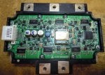
The HCH1 MCM detects the system voltage using the battery voltage tap inputs.
It does not appear to have a second voltage check from the IGBT/driver module like the G1 Insight does ;)

Edit Looks like I was wrong about this.

The G1 Insight uses voltage taps for the BCM voltage detection, but this is compared with a special voltage check analog signal that the IGBT sends to the MCM. These two values are compared by the MCM, and so both had to be faked to enable a voltage hack mode in the G1 Insight. Quite difficult and a bit of a PITA.

With the HCH1 it appears only to have one voltage sensing system (via the taps), which is faked in my Lithium pack by the BCM fooler resistor matrix, and made adjustable with the addition of the pot on the + end to fake a lower system voltage if reqd.

I may simply be able to turn the detected system voltage up and down with the simple pot and the actual battery voltage will determine the IMA power. We already know the car tries to compensate for an apparently lower system voltage by increasing IMA current so we get a double bonus :)

Only a test will determine if some other voltage detection is being implemented but from study of the data and the IGBT data sheet etc I don't see anything. Fingers crossed!

PS I saw 90A briefly from my stock HCH1 setup today as battery temp was 25c or so. So I might simply fake the oem NTC battery thermistors for a static 30C battery temp to ensure the IMA will deliver full current with my Lithium setup. I need to take some measurements of their resistance at 25-30C or so.
 
#2 ·
Just looking at the temp sensor charcteristics they are given in the advanced diagnostics as 10k at 25C (77F) that sounds like a good number to start with so I will make a up another dummy temp sensor plug for my HCH1 Lithium set up with 3 x 10K resistors for the NTC sensors and 1 x 20R for the PTC strips. That should give optimum IMA temp current performance.
 
#3 · (Edited)
Voltage Checks

Further study of the HCH1 advanced diagnostics and manual indicates there is a voltage check between what the MCM detects via the voltage taps and what the IPU detects in the IGBT. Now there is no DAC VPIN in the IPU like in the G1 insight so a simple analog hack won't work as there is no line to tap into. The advanced diagnostics indicate a difference of more than 10V between the MCM and IPU voltage will trigger an error, this is the same as the G1 Insight.

The manual goes on about serial comms between the IPU and the MCM on the IPUA line. So the only place the voltage data can be is on this line perhaps in a packet of data with the IPU temp signal and fail flag data.

I feel another pic 12F683 interceptor project comming on to filter this data and pass thru lower voltage signals. I'l try and capture some basic data later today. It should be farily easy to see the voltage byte in any data, as when the car first turns on the bypass contactor operates and we should see a fast/steep rise in a value as the IPU capacitors charge up prior to the main contactor operating. If I measure the voltage before we start and once the charge cycle is complete it should allow us to establish a relationship between the serial data value and the IPU voltage.
 
#4 ·
Captured data

Captured some data from the IGBT IPU powered up on the bench.

Quite a few packets being sent at what looks like 9600,8,N,1 but I also powered up the HV side of the IGBT and turned my 0-300V psu up and down while capturing the packets so should be able to work out which one is the voltage byte.

A123 Civic 012 - YouTube
 

Attachments

#5 · (Edited)
Spreadsheet Challenge

OK here is a spreadsheet of some captured IPUA data.

The serial data is made up of 5 repeating packets of 6 bytes.
Each packet contains 4 data bytes and a header and chksum byte.

Can you spot a pattern or corelation between the voltages I was applying and the data.

Comments and assistance welcome. :)
 
#6 · (Edited)
Man, those numbers are all over the place.

I can see a good correlation among your data in the 0-100v sheet. Starting at line 66 you can see all the data in the last four runs does the same approximate thing, but what that is, I'm at sea about.

Just looking at the 0-100v runs here:

The middle two bits don't seem to do anything related to voltage output. The numbers are different between the runs, but stay constant throughout... no idea what's up with that except that they give some kind of state? Except that first run, but it seems to be "flickering" I don't know if that's a bad connection, or what.

If it's 6 data bytes (byte 0 being the Id and byte 5 being the Chk), bytes 1 and 4 seem to be the entirety of the real data. Byte 4 seems to only toggle between 0 and 160 (0 and 10100000). The toggle seems to alternate with changes in the byte 1 value, I find this to be a pretty telling series (lines 67-71 in the second 0-100v run):

Code:
Byte 1		Byte4
00000000	10100000
10000001	00000000
10000010	10100000
00000011	00000000
10000100	10100000
Looks like byte 4 toggles its value between each incremental change of Byte 1. The first bit of byte 1 looks like it's lockstep with byte 4 here, but later you get this (shortened to unique values only):

Code:
Byte 1		Byte4
00000101	10100000
00000110	00000000
00000110	10100000
10000111	00000000
10000111	10100000
10001000	10100000 *Might there be a missed value here?*
00001001	00000000
00001001	10100000
 
#7 · (Edited)
I'll double check my data and capture some more later. Capturing data from the IGBT module on the bench might not work as most of the I/O is not connected and perhaps the voltage detection in the module is disabled when it's not driven. Might have to gather data from a live car.
 
#8 · (Edited)
I captured some more data from another IPU on the bench but the data is still eratic with no obvious corelation between IGBT input voltage and a byte in the data stream it outputs, looks like I will have to treble check it with a live car.
 
#9 · (Edited)
#10 ·
I had assumed my logic analyser had worked out the correct format for the serial data before I imported it into excel. Duh !!! I was a bit surprised it had no parity as most of the other Honda stuff i had studied does, so when I changed the analyser settings and forced it to have even parity the data changed significantly and there is now a clear corelation between igbt input voltage and the first data byte in each packet. Oh well at least I have found the issue. See attached.

The MPI Voltage is the first byte in each packet x 2, that makes sense and coreleates with the fact the mpi voltage jumps by two volts at a time when being monitored by the honda scan tool.

Now I can work on the interceptor.

I shall delete my prev posted spreadsheets! :roll:

http://www.insightcentral.net/forum...iscussion/4163d1357414858-hch1-a123-60ah-pack-install-010113_0-200v-data-ep.zip
 
#11 ·
Yep, it jumps right out at you now :). There are going to little pics running all over your car soon.

Curious, what format is that file on the fan data?
 
#13 · (Edited)
The prototype Data interceptor using the 12F1822 pic works on the bench with an HCH1 IPU IGBT powered up as the data source. The data stream passes straight thru the pic unchanged at present and basically runs a byte behind the data comming from the IGBT.

The baud rate is ~10400 as near as I can figure it, which is a standard rate for serial protocol.

Need to add the data modifying code now.

I'll probably just program in a fixed setting and I'll start with Voltage - 20V so the MCM see's a more reasonable voltage ~170V. I'll have to adjust my voltage tap pot to the same level.
I can tweak it down more later and use the Honda tool to display the Bat V and MPI V so they match better than they do now.

Edit
I think I have the voltage mod code sorted now, I will test it tomorrow it's been a busy day ;)
I can see I will need to change that pot on my fooler matrix for a 100k version to get a bigger range.
With 100k I would be able to pretend voltage was between 100 - 50% of it's true value!
 
#14 ·
Fixed versus variable system voltage?

Just to recap the HCH1 like the G1 detects the system voltage in two places.

1) Via the battery voltage taps, which gives stick pair voltages and a total voltage for the pack.

2) Via the Vpin from the IPU/Igbt Driver board which gives the voltage present at the IGBT power input.

It compares and uses these voltages in the MCM for various functions, including IMA power & current control, main contactor engagement, battery management.

Now we can simulate the battery voltage taps using the very simple 10 x 10k 1% resistor matrix to provide a perfectly balanced input. We can reduce the voltage the system see's with the voltage taps by adding an extra resistor on the + feed to the matrix to give a lower voltage.

We can now also intercept the voltage reported by the Vpin/Igbt data and manipulate that as we wish.

Now the question is should we opt for a fixed lower system voltage or a variable one but with a reduced maximum voltage.

Scenario 1

Add a 20k resistor to the matrix + feed and get battery voltage - x%
Program the Ipu Interceptor to match the % reduction provided by the 20k resistor.
This will give variable current as the voltage rises and falls and operate much as now.

Scenario 2

Feed the resistor matrix from a HV supply provided by a zener diode so it is fixed at say 150V. Program the Ipu Interceptor to fix the Vpin system voltage at 150V. This will give higher current the lower you fix the voltage down to about 125v minimum. However if you fix the voltage below about 140v then IMA start won't work and soc might neg recal all the time and forced charge will be active. So there is a trade off there. I overcame this with the G1 by having a special Voltage boost mode which faked a fixed voltage of around 130V only when maximum assist was being called for, in that situation the car was expecting a lower voltage and ramped up the current accordingly.

The programming of the Ipu interceptor also has to take into account.

1) The MCM uses the fast rise in Ipu voltage when the car is first turned on and the bypass contactor is engaged to charge the filter capacitors and work out when the main contactor can be safetly engaged.

Just a few random thoughts.
 
#15 · (Edited)
Well interceptor seems to work fine. Voltage is faked at Bat V - 24v which brings it down to around 165v and regen is now operating again :) Resistor fooler is adjusted to match the IPU interceptor. Lined them up using the Honda Tool to display both voltages.

http://youtu.be/ixz5WtQDU-4
 

Attachments

#16 · (Edited)
Looking for the temperature data

HCH1 Civic IGBT Power Increase Research Video 3 - YouTube

I don't need it for the project, but for completeness be useful to know which is the temp byte.

Edit

Temp is data byte two in the D2 packet.

Data byte three may also be temp related, but possibly from a heat or ambient temp sensor on the driver board which did not get anywhere near as hot as the base plate I was heating up.
 
#17 · (Edited)
+30% Current Hack

Tried the simple resistor current hack for +30% Current. gave some IMA errors as expected.

Worked well for assist but gave IMA regen errors above about 45A at low rpm.

Also had problems starting and going into autostop.

Anyway will try the +18.5% version next week.

Need to pull the codes now and have a look at what's what.
 
#18 · (Edited)
IPUA Data Gathering

Gathered some live data from the IPUA line from the IGBT to the MCM as the error given with the +30% mod was Motor short circuit. (Not hacked current sensor errors) The only comms from the IPU (IGBT) to the MCM is over the IPUA serial line so there must be a flag in there that is being set.

To be fair the error does not appear under hard assist or moderate to heavy regen at > 1000 rpm. Performance is very lively as you would expect

The problem appears when the motor is starting/autostarting from stop or autostoping under car heavy regen/stop command. This is when motor is stopped or turning over at slowest and when back emf is low and current is at it's peak. Probably also when motor is being driven with square wave instead of sine wave pwm IIRC but I haven't looked at the HCH1 drive waveforms yet to confirm this. If it is using a hard square wave pwm at say < 1000 rpm then current will shoot up when the motor is starting/stopping.

Interestingly the G1 insight does not suffer so much from this problem when using higher current perhaps due to the fact it's a lighter engine internals and only 3 cylinders, so the starting torque reqd is less, which means it spins up more easily and doesn't stress the IGBT. Vice versa for autostop which reqs more regen to stop the four cylinder HCH1 and so the current doesn't fall away so quickly as it does in the G1 3 cylinder lightweight engine crank etc. Just a possible explanation.

So the basic problem with +30% current is igbt overcurrent alarm when starting/stopping/low rpm.

Possible solutions.

1) Abuse the IGBT and find the over current flag in the IPUA data and suppress it! I already have an interceptor on that line to monitor/control the detected voltage and igbt temp etc. Fairly easy to do but may not be good for the IGBT longevity. The IPUA data I have captured today should contain the flag as I have forced the error several times stopping/starting and driving around. The fact the error does not appear every time means it's right on the limit, so it is not consistently overcurrent. Probably due to the exact position of the engine crank/pistons etc when it is stopped i.e. right at bottom/middle/top of a compression/ignition stroke so more resistance to initial start/stop torque on start/stop cycle.

2) The commands to start/stop the engine come from the ECM over the MOTA line which has my IMAC&C installed. So I could use that to look for the IMA start/autostop commands from the ecm and then modify the start/autostop assist/regen level commanded and reduce it by say 30% before passing it to the MCM. That may do the trick.

Anyway I'll try adjusting the IMAC&C to start with. I like the extra omph and the nice whine the motor/electronics makes under the higher current so I want to crack the problem.

Dave Hancock (HCH1 IMAC&C owner and ex Honda Mechanic) came over yesterday and we had a good play about with some stuff. It was whilst talking/brainstorming with him that I had the idea about using the IMAC&C to modify the start/stop/low rpm regen commands. It's always useful to have other ideas thrown in.
 
#19 · (Edited)
Suppressing IGBT IMA Errors

Well I found the byte and tried suppressing the IGBT error flag bit in the IPUA data stream and that works. ;)
No IMA codes or system shutdown.

The IPU (IGBT) still shuts itself down (protects itself) momentarily and you now feel the motor stutter for a millisecond then it carries on as normal. I'll see how it goes.

Regen current is the most stressing for the unit and that is running at 70A+
Slowing down with high regen from high rpm/speed does not cause the over current error until the revs fall to around 1000rpm when you feel the igbt cut out briefly. (Switch over from sine to square wave or vice versa?)

I might add a simple led to the dash (Controlled by the IPUA Interceptor) so I can see when the igbt shortcircuit/overcurrent flag is being set. Constantly clearing IMA errors was a PITA. (I don't have to do that now which is nice!)

This testing is with +30% current and 180V * 82A = about 14.7kw

Edit. just back from 40 mile trip and a couple of good hills seems to work well.

Now to transfer this research to my G1 project car and boost the current on that :)

PS I tweaked up the IPU fan a bit as well for some extra cooling. Saw IGBT 50C max on the trip.
 
#20 ·
Glad to see you got that one sorted Peter, it really did make a big difference to the usable power the car had and the gentle hum of the electronics in the back really makes some sweet sounds!

Sent from AutoGuide.com App
 
#21 · (Edited)
This car would be perfect for a sleeper, just take off along side a camaro or mustang and cancel assist Off after leaving the stoplight, get quickly ahead to bail him. As you hear him gas it to pass you, click assist on.
It should jump instant about 80-100 % Regen at about 2.500 rpm and the car really literally jump pass the car beside you and hit 40 in a few second, try it, here it better.:)
 
#23 ·
Whoa that's cool.

How much work is involved with the installation?
 
#24 ·
I'm reverting to a standard MCM for the time being. The IGBT short circuit warning is coming on too often for my liking at +30%.
I'll do/try the voltage mod instead and fake a lower system voltage so the car allows more current within it's natural limits.

I'll try the two stage current mod later when the pcb's arrive.